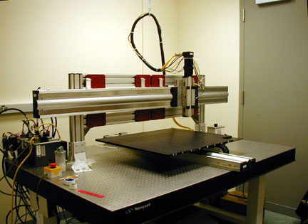
The Linear Servo Arrayer is similar in overall design the arrayer outlined in the MGuide, however it is vastly improved, and uses different hardware. The slide platter is bigger, nearly doubling the capacity to 260 slides per run. In addition the glass is held down by vacuum, making the set-up and take down of a print run much easier than before.
The linear servo arrayer is a computer controlled xyz robot. Though it seems complicated, it is simple enough to construct yourself. By analogy, if you have a sound card in your computer, you already have experience using your computer to control electromagnetic motion. Just as your computer can give input to the sound card to control an amplifier and modulate electromagnetic motion within a speaker, your computer can also give commands to a motion control card that modulates the motion of robotic slides allowing you to control motion in three dimensions for array printing.
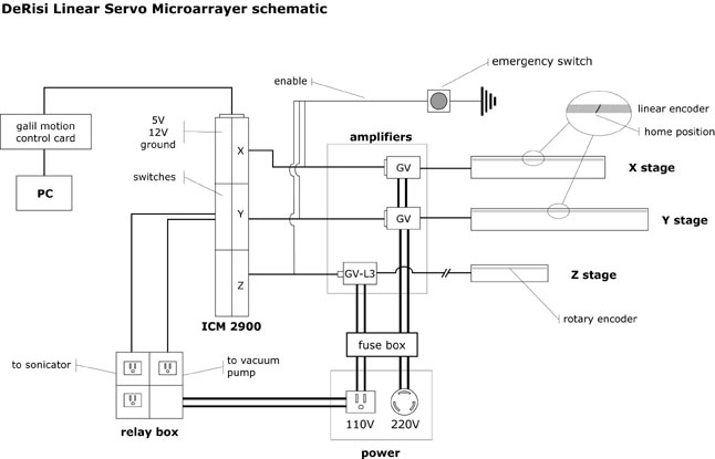
The computer controlled robotic array system is diagrammed below. Galil is a motion control company that makes a special card which you install in your computer (PC), the same way you would install a sound card. Galil has also created software libraries containing functions and commands for motion control, so that you can write programs that interact with the card (Joe DeRisi used these libraries while writing the ArrayMaker software). The card is connected to a wiring bus called the ICM2900. The wiring bus serves as a physical manifestation large enough for conveniently wiring input and output to the card. It has 4 regions for controlling specific axes of motion - though only three are used for the arrayer, and several electronic switches, as well as lots of standard features that are common for electronics projects, such as power in standard voltages (5V, 12V), and ground outlets. The wiring bus is connected to all the other electronic components of the arrayer, such as the amplifiers. The card controls the motion of each axis by manipulating small voltages, which are then amplified into the large amounts of power required to drive the stages by the GV amplifiers (the amplifiers are also known as motor drivers). Each stage on the wiring bus contains a slot for a pair of "enable" wires. The enable wires are used for the safety switch. For a stage to be able to move, the enable wires for the stage must form a closed circuit (i.e. they must be shorted). All three pairs of wires are wired into the safety switch, which is closed by default. Upon hitting the safety switch, the circuit is opened, and the stages will no longer be "enabled" function.
The wiring bus also contains a few switched outputs which are used for the vacuum and sonicator. These switches, are simply low voltages which are switched on or off. The relay box contains relays which are driven by the low voltage. For instance, to turn on the vacuum, a low voltage is switched on which activates a relay in the relay box. Activating a relay allows wall power to flow and power the vacuum. The vacuum pump draws too much power to be powered directly by the controller card, so a relay box is used to bridge the gap, and control the connection between the vacuum pump and wall power (110V).
Each stage keeps track of its motion by using an encoder. An encoder is a strip of metal etched with little marks. In our case the marks are exactly 1 micron apart. As the stage moves it counts encoder marks and reports them back to the computer. In order to define a reference point by which all movements can be calculated, the encoder strip contains a unique marking called "home" which is wider than the other markings. Once the machine knows where the home mark is, it has a way of moving to any desired position.